The USB Digital I/O Commander, herein referred to as simply
"Digio",
provides a powerful means of interfacing your computer to external
devices
via digial I/O signals. Compatible with desktop and laptop
systems,
Digio allows a Windows PC to set digital outputs and/or read digital
inputs.
You can use Digio as a means of controlling external devices.
While Digio can perform simple "set" and "get" operations, its
real
strength lies is its ability to define notification action(s) when
input
signals, also referred to as "trigger signals", change state.
You'll
find Digio an important tool for use in a variety of applications
including
industrial control, hardware design, and prototyping.
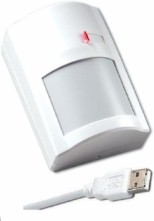
Digio is compatible with the USB Motion Detector which is
comprised of an infrared detector and internal USB I/O module
(U4x1). The USB I/O module has integrated cable which connects to
an available
USB port on your computer. The module provides 16 I/O signals
configurable
in any combination of inputs and outputs. The system is easily
expanded
by simply adding more USB modules.
Becoming familiar with a new tool can sometimes be a daunting
task.
Many times a real-world example provides the insight needed to gain
confidence
and understanding. This tutorial describes how to use
Digio to configure a real-world USB security system consisting of PIR
motion
sensor, 10 door/window sensors, horn/siren relay, and USB interface
(U4x1).
(For details on purchasing a USB motion detector plus Digio software,
refer
to the USB
Motion Detector page at the Kadtronix
website.) For details on Digio software including system
requirements,
installation, and descriptions, you can view the Digio User
Manual online.
-
Wiring and Hookup
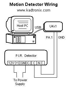
The following diagram shows the USB security schematic including motion
detector, door/window sensors, and U4x1 interface. Also included
is a reed relay for horn/siren activation.
(Note: For proper operation, be sure to enable internal U4x1 pull-up
resistors using Digio software.)

The following image shows how to wire a standard PIR motion
detector.
An external source is required for powering the detector.
(Note: The Kadtronix USB
Motion Detector is pre-wired and requires no
external power source as it derives its power directly from the USB
cable. No additional wiring or assembly is required.)
-
Start Digio Software
Before beginning, you should plug your U4x1 device into an available
USB
port on your computer. If all ports are occupied, you should
obtain
a USB hub which will expand the number of available ports. Now,
activate
the Digio program by selecting:
Start Menu -> Programs -> USB Digital I/O Commander for
LAN
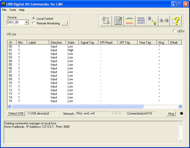
When the program begins, the main display dialog appears as shown
below:
On first-time start-up, you will be asked to register your
software.
Fill in the requested fields and click "Send" to submit your
registration
data.
Your software may require a license key for activation. If
so,
a key will be provided to you via e-mail after purchase. The
license
key is an encoded string consisting of a series of alpha-numeric
characters.
When you receive the license key, select the following main menu item:
Tools -> Enter License Key...
Enter the encoded key string in the "Enter key:" field as shown
in the example below. Then, click "OK" to accept the new key and
enable the application.

-
Adjust System Properties
For proper operation of the security system application, you will
need to make some settings adjustments within the properties
page.
To open the properties page, make the following menu selection:
Tools -> Properties
Make the settings adjustments as shown below:
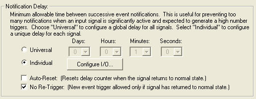
Of particular importance are the notification delay settings
shown below.
Be sure to activate the "No Re-Trigger" check-box. This
will
ensure that alarms do not re-trigger falsely.
If you plan to use the automatic e-mail feature, you must configure
e-mail
properties. Click the E-mail "Properties" button located at the
bottom
left section of the page. The following dialog image will be
shown:
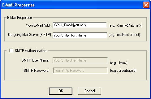
The following parameters are required for email notifications:
-
Your email address (e.g., jimmy@att.net)
-
Outgoing (SMTP) mail server (e.g., mailhost.worldnet.att.net)
The program is compatible with systems where e-mail is implemented
on networked servers. In this instance, simply enter the server
name
in the "Outgoing Mail Server" field.
Specify the following parameters only if SMTP authentication
is required:
-
SMTP user name
-
SMTP password
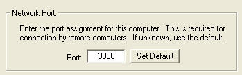
Click the "OK" button to save your e-mail settings and return to the
global properties page. The bottom ritght section of the page
provides
a field for supplying a network port number. This value is needed
to allow remote machines to connect to your computer for monitoring
purposes.
(This field is required only if you have purchased the multi-user LAN
product.)
Now that you have completed the properties settings, close
the dialog
by clicking "OK".
-
Configure I/O Signals
It's time to configure your I/O signals. This step is required
for
defining which of the U4x1 signals are inputs and which are
outputs.
There are 16 total signals provided by the U4x1, each individually
configurable.
Your USB security system will use 12 signals in all: 1 output plus 11
inputs.
To configure the device, make the following menu selection:
Tools -> I/O Control...
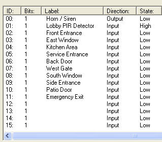
Use the "Device" combo-box to select the device as shown.
Digio can accommodate multiple U4x1 devices, but our security system
application
uses only 1 device and it will be designated DEV_00.
Additional
USB devices would be designated DEV_01, DEV_02, etc. You should
establish
directions (input/output), states (high/low), and label descriptions as
shown. (Note: It is not necessary to set the high/low state
on inputs since they will be determined by the software automatically.)
Also enter default notification delay values as shown.
Notification
delays are used to prevent an overload of notifications on very active
inputs. The "Default" column defines the beginning
countdown
value when a trigger event occurs. For instance, a value of
30 indicates that a minimum delay of 30 seconds is required between
successive
alarm trigger notifications.
An important setting to note is the check-box located in the upper
left region of the dialog.
Use this check-box to enable internal pull-up resistors within
the U4x1.
This setting is required for proper operation of the USB security
system.
It ensures that when the motion detector senses activity, a logic high
signal will be received at the U4x1 device.
After completing the fields, click "OK" to save your
selections, exit
the dialog, and return to the main display. It should now contain
a summary of your recent settings changes as shown below:
-
Define Events
Now that you have configured the inputs and outputs, you can create
events
and attach them to your signals. These event associations define
alarm ("trigger") conditions and the action(s) to perform. You
can
also think of these actions as notifications. To define
notifications,
select the following menu item:
Tools -> Attach Events...
You will notice that most of the fields have been grayed
(disabled).
This is because the selected signal ("00") is configured as an output
for
horn/siren activation. Since events are defined for inputs only,
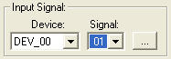
you will bypass this signal and go to signal "01" instead. To do
this, left-click the mouse on the "Signal" combo-box and select "01" as
shown below:
The following display will be shown whose contents represent
the PIR
motion detector:
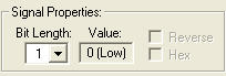
First, ensure that the defined bit length is "1" as shown in
the image
below:
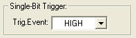
Next, locate the region titled "Single-Bit Trigger" and select
"HIGH"
as shown below. This assumes the normal pre-trigger state is LOW
and that detected motion will cause the signal to become HIGH.
Since you will not be using SPI triggers or Time/Day triggers,
you should
keep them disabled. It's now time to define some
notifications.
Remember that these are the actions to take when the PIR motion
detector
"triggers", i.e., detects movement. There are 8 possible
notification
types. You will define four actions to perform: display a message
on the monitor, send an e-mail message, set a signal output, and play a
sound file. Left-click each check-box to enable the four events
as
shown below:
You will notice two rows of buttons to the right labelled
"Select..."
and "Preview". Use the select buttons to define events and the
preview
buttons to test them.
Now, left-click the first (upper) "Select..." button
associated with
the "Display Msg" selection. Enter the message text,
"Motion
detected in front lobby" as shown. This text message will be
displayed
on your computer's monitor when the event occurs. Use "Auto" to
automatically
extinguish the message after the specified number of seconds.
Click
"OK" to save the selections, close the dialog, and return to the
previous
page.

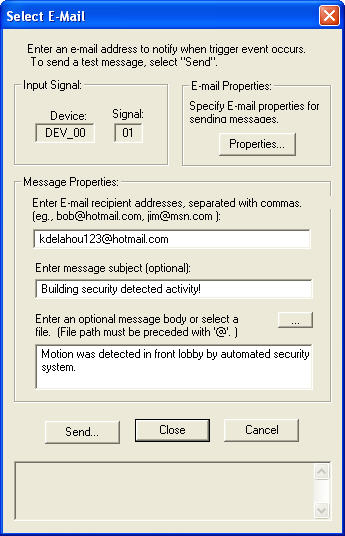
Left-click the "Select..." button associated with the "Send
E-mail"
selection. This allows you to designate an e-mail message to
occur
in response to an event. Choose the desired e-mail recipient(s),
message subject, and body. If you have not already dones so, be
sure
to specify e-mail properties using
the
"Properties..." button. Click "Send" to send a test e-mail
message.
Click "Close..." to save the selections, close the dialog, and return
to
the previous page.
Next, left-click the"Select..." button associated with the
"Set Output"
selection. This will allow you to activate the horn/siren
relay
in response to detected motion. Make the selections as shown,
being
sure to choose output signal "00". Also check the "Enable Toggle"
box and specify a time delay. This will cause the siren to
automatically
de-activate after the defined time period. Click "OK." to save
the
selections, close the dialog, and return to the previous page.

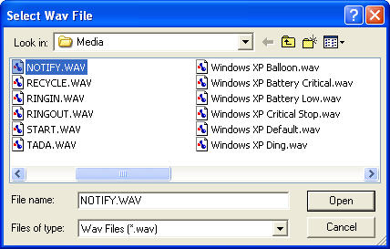
Now, left-click the "Select..." button associated with the
"Play Wav"
selection. A file browser dialog will appear, allowing you
to choose the desired sound file. This file will be played when
the
alarm event occurs. Click "Open" to save the selection, close the
dialog, and return to the previous page. Use the "Preview" button
to play the selected sound file.
Now that you have defined the four alarm notifications for
signal "01",
your events page should resemble the following:
Next, define event associations for the remaining
inputs: 02 through
11. Follow the same procedures as described above, beginning with
input signal selection as shown below:
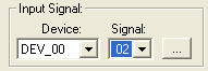
Since signal 02 corresponds to the "Front Entrance", you
should define
messages that appropriately describe this input. You have the
flexibility
to define any subset of the 8 available notification types. If
you
choose to remove or disable a notification, simply left-click the box
to
remove its check-mark.
-
Test
You're now ready to perform a test. Before starting, close the
Digio
application, being careful to save your program settings. Next,
plug
the U4x1 device into an available USB port on your computer.
Apply
power to the motion detector and then start the Digio software once
again.
You should see a status message near the bottom left segment of the
Digio
display that reads, "1 U4x1 device(s)!", indicating the U401 was found.
There is a small red indicator light on the front of the
detector unit
that illuminates when movement is detected. While viewing your
computer's
monitor, walk in front of the detector or have an assistant do
so.
You should notice a pop-up message on your monitor as shown below:

If you configured this message as suggested earlier in the
tutorial,
it will be shown for several seconds and then automatically
extinguish.
If you have designated audio (.wav sound) and/or e-mail notifications,
make sure they also trigger. If they do not, check the Digio
configuration
to determine if they are properly defined and enabled. Test the
horn/siren
relay with a multi-meter. Attach leads to the unsoldered contact
connections and check for continuity. The relay will be
activated
for 20 seconds before de-activating automatically.
-
Appendix I: USB I/O Module
The USB I/O Module provides the interface between your external
hardware
and the PC. Made by USBmicro, this module is available in two
form-factors and provides 16 signal lines,
configurable in any combination of inputs and outputs.
The following tables present pin-out information:
U401 Interface Connector Pin Out
| Pin Number |
USB Interface Signal |
| 7 |
+5V USB from PC |
| 9 |
GND |
| 15 |
PA.0 -
Port A bit 0 |
| 16 |
PA.1 -
Port A bit 1 |
| 17 |
PA.2 -
Port A bit 2 |
| 18 |
PA.3 -
Port A bit 3 |
| 19 |
PA.4 -
Port A bit 4
[SPI SS (slave-mode only)] |
| 20 |
PA.5 -
Port A bit 5
[SPI MOSI] |
| 21 |
PA.6 -
Port A bit 6
[SPI MISO] |
| 22 |
PA.7 -
Port A bit 7
[SPI SCLK] |
| 23 |
PB.0 -
Port B bit 0 |
| 24 |
PB.1 -
Port B bit 1 |
| 25 |
PB.2 -
Port B bit 2 |
| 26 |
PB.3 -
Port B bit 3 |
| 27 |
PB.4 -
Port B bit 4 |
| 28 |
PB.5 -
Port B bit 5 |
| 29 |
PB.6 -
Port B bit 6 |
| 30 |
PB.7 -
Port B bit 7 |
U421 Interface Connector Pin Out
| Pin Number |
USB Interface Signal |
| 14 |
+5V USB from PC |
| 9 |
GND |
| 1 |
PA.0 -
Port A bit 0 |
| 2 |
PA.1 -
Port A bit 1 |
| 3 |
PA.2 -
Port A bit 2 |
| 4 |
PA.3 -
Port A bit 3 |
| 24 |
PA.4 -
Port A bit 4
[SPI SS (slave-mode only)] |
| 23 |
PA.5 -
Port A bit 5
[SPI MOSI] |
| 22 |
PA.6 -
Port A bit 6
[SPI MISO] |
| 21 |
PA.7 -
Port A bit 7
[SPI SCLK] |
| 5 |
PB.0 -
Port B bit 0 |
| 20 |
PB.1 -
Port B bit 1 |
| 6 |
PB.2 -
Port B bit 2 |
| 19 |
PB.3 -
Port B bit 3 |
| 7 |
PB.4 -
Port B bit 4 |
| 18 |
PB.5 -
Port B bit 5 |
| 8 |
PB.6 -
Port B bit 6 |
| 17 |
PB.7 -
Port B bit 7 |