| This
page describes how to properly wire the MCAS and interface with your
hardware. Interface to the MCAS controller occurs through two 40-pin
header sockets: J4 and J5. (Refer to the MCAS
User Manual for pin-outs and pin descriptions.)
Kadtronix
now offers a Field Wiring Terminal Board (FWTB) for
easy interfacing. Features screw terminal block, power switch, flashing
LED indicator, AC power jack, and onboard door activation relay.
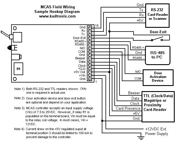
The
following schematic image illustrates a typical MCAS application including
card-reader, host-control interfacing, and door-activation connection.
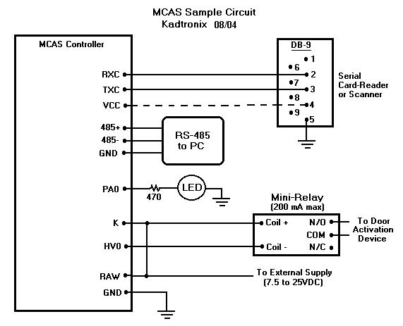
| Note
1: Card-readers have different pin-outs and voltage requirements.
Consult your specific device's documentation for hook-up information.
Note
2: Also required (not shown in the diagram above) are pulldown
resistors at MCAS controller signals PD0 (J5-19), PD1 (J5-20), and PD2
(J5-21). Refer to the MCAS
User Manual for details.
Note
3: The diagram above indicates a RS-232 card-reader. A
TTL (clock/data) reader, proximity reader, or barcode scanner may
also be used. Refer to the MCAS
User Manual for details. The dashed line indicates a port-powered
connection where the reader device obtains its power from the serial port.
If using a MagTek serial RS-232 card-reader such as part number 21040075,
use one of the following wiring guides: |
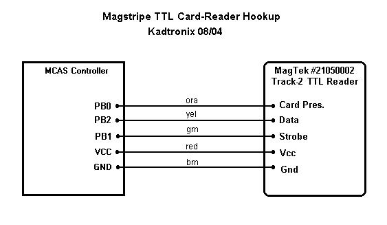
| The
following schematic image shows how to wire a MagTek #21050002 magstripe
TTL card-reader: |
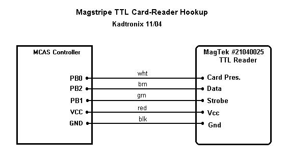
| The
following schematic image shows how to wire a MagTek #21040025 magstripe
TTL card-reader: |
| The
following schematic image shows how to wire a Kantech, Polaris #POL-2 &
#POL-2KP magstripe TTL card-reader: |

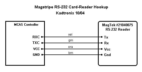
| The
following schematic image shows how to wire a MagTek #21040075 magstripe
RS-232 card-reader: |
| The
following schematic image shows how to wire a MagTek #21065095 magstripe
RS-232 insert card-reader: |

| The
following schematic image shows how to wire an IDTECH # IDT3321-12B
magstripe RS-232 card-reader: |

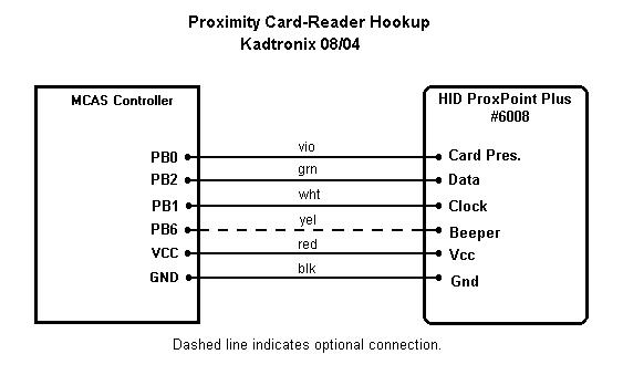
| The
following schematic image shows how to wire a HID #6008 proximity TTL card-reader: |
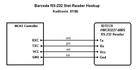
| The
following schematic image shows how to wire an IDTECH #WCR3227-600S RS-232
barcode slot-reader. |
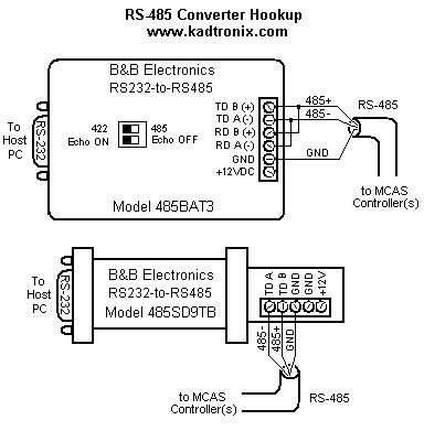
| Host
communication requires a RS232-to-RS485 converter. The diagram below indicates
two types of converters made by B&B
Electronics: models 485BAT3 and 485SD9TB. Both devices are port-powered
and feature optional +12VDC external power connections. |
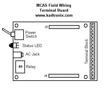
| The
Field-Wiring Terminal Board (FWTB) allows easy interfacing and provides
two header connections for mating with a MCAS controller. In addition,
it provides 16 screw terminal connections for interfacing card reader,
RS-485 cable, and power supply. The terminal board also provides
power switch, flashing status LED, AC jack, and door activation relay.

Kadtronix
now provides a special Ethernet (TCP/IP) option for LAN users. This
new feature (FWTB option 3) includes integrated RJ-45 jack for easy
interfacing. |
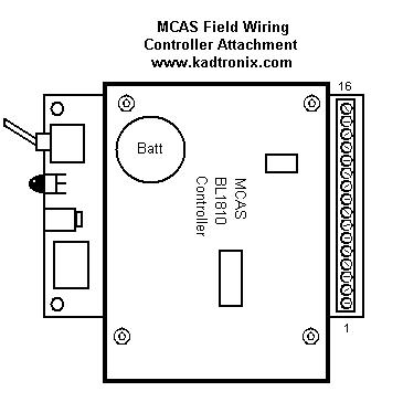
| All
soldered FWTB components are optional (except header connectors and terminal
block) and need not be populated if desired. A "bypass" jumper" can
be soldered in place of the power switch. The following diagram shows
orientation and placement when attaching a MCAS controller to the FWTB. |
| The
following image illustrates hookup and interfacing details. (FWTB
shown without MCAS controller for clarity.) |
|
(
Optional A/C power jack may be used instead of power input at terminals
1 & 2 if desired.)
|
FWTB
Terminal Connections
(Option
1 - RS485 Host Comm.)
|
1
|
Ground |
|
2
|
Vin |
|
3
|
+5V out (100mA max) |
|
4
|
Card presence (TTL magstripe &
proximity readers) |
|
5
|
Clock input (TTL magstripe &
proximity readers) |
|
6
|
Data input (TTL magstripe &
proximity readers) |
|
7
|
Beeper input, optional (proximity
readers) |
|
8
|
Ground |
|
9
|
Door/gate activation relay contact
- COM |
|
10
|
Door/gate activation relay contact
- N/O |
|
11
|
Host comm., RS485 - |
|
12
|
Host comm., RS485 + |
|
13
|
Door exit button input (active-high) |
|
14
|
Tx - Transmit signal output (RS-232
card-reader, 9.6K baud) |
|
15
|
Rx - Receive signal input
(RS-232 card-reader, 9.6K baud) |
|
16
|
Ground |
FWTB
Terminal Connections
(Option
2 - RS232 Host Comm.)
|
1
|
Ground |
|
2
|
Vin |
|
3
|
+5V out (100mA max) |
|
4
|
Card presence (TTL magstripe &
proximity readers) |
|
5
|
Clock input (TTL magstripe &
proximity readers) |
|
6
|
Data input (TTL magstripe &
proximity readers) |
|
7
|
Beeper input, optional (proximity
readers) |
|
8
|
Ground |
|
9
|
Door/gate activation relay contact
- COM |
|
10
|
Door/gate activation relay contact
- N/O |
|
11
|
Tx - Transmit signal output (RS-232
card-reader, 9.6K baud) |
|
12
|
Rx - Receive signal input
(RS-232 card-reader, 9.6K baud) |
|
13
|
Door exit button input (active-high) |
|
14
|
Tx - Transmit signal output (RS-232
host comm., 115K baud) |
|
15
|
Rx - Receive signal input (RS-232
host comm., 115K baud) |
|
16
|
Ground |
|