
User Manual
Version 2.1.7
2/14/08
Copyright (C) 2003 - 2008
All rights reserved
Kenneth Delahoussaye Consulting
in association with Kadtronix
web: www.kadtronix.com
email: kdelahou@worldnet.att.net
Table of Contents
-
Introduction
-
System Requirements
-
Card-Reader Compatibility
-
Features
-
Ordering
-
Installation
-
Program Operation
-
Communication Settings
-
Adding Reader Stations
-
Adding Users
-
Saving
-
Manual Commands
-
Enabling Stations
-
Tools
-
Poll Stations
-
Auto-Detect Stations
-
Open Door/Gate
-
Monitor Card-Access
-
View Access Logs
-
Clear Card-Access History
-
Configure Auto-Upload
-
Configure LAN devices
-
Set Station Date/Time
-
License Registration
-
Card-Reader Controller
-
Hookup Diagram
-
Pinouts
-
Connecting a Power Supply
-
Connecting a Door Activation
Device
-
Connecting a Door-Exit Button
-
Enabling RS-232 Host Communication
-
Firmware Upgrades
-
Resources
-
Legal
-
License
-
Warranty
-
Introduction
The Magstripe Card Access System (MCAS) is the basis of a home, office,
or industrial access control system. The MCAS system consists of card-reader
(or barcode scanner), smart controller (BL1810 or OP6700), personal computer,
RS-485 adapter (or Ethernet), and control software. The system is
easily expanded. Using MCAS host control software, users may be added
at any time to a maximum of 1000 (or 250 for OP6700). In addition,
several host communication protocols are supported as shown in the table
below:
|
Host Comm. Protocol
|
|
RS-485
|
|
RS-232
|
|
Ethernet (TCP/IP)
|
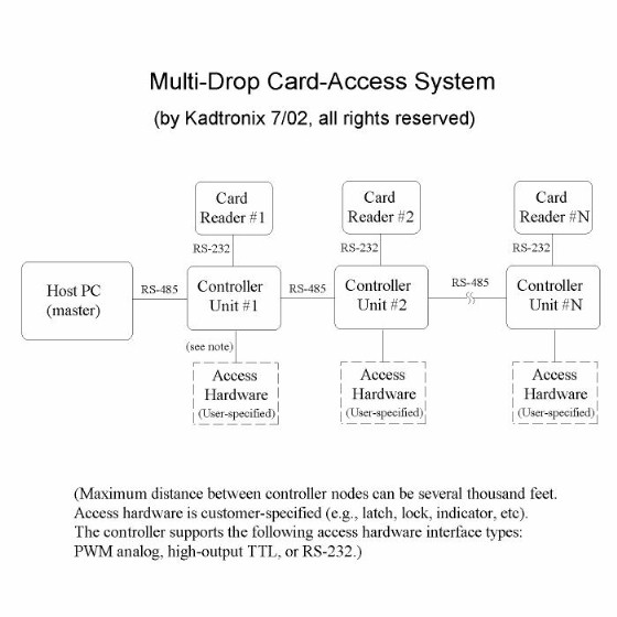
RS-485 is the default communication protocol. The network supports
up to 32 card-reader controllers, all networked on a single serial communications
cable. Supporting an array of commands, the MCAS control software
allows you to add, modify, or remove users. Also set configuration
parameters such as activation method, time delays, etc.
The following diagram depicts the high-level MCAS components:
The BL1810 controller is a single-board computer featuring onboard battery-backed
SRAM user database, Rabbit-2000 processor, and RS-485 multi-drop communication
link. It can accept magstripe or RFID proximity readers. Supported
reader interfaces include RS-232, TTL (clock/data), and Wiegand.
It also has the capability for optional serial RS-232 host comm.
Although the BL1810 does not include Ethernet capability, Kadtronix can
apply an add-on option if desired.
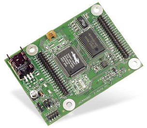
Low-Cost BL1810 Controller
If desired, you may obtain the OP6700 operator interface terminal.
Like the BL1810, the OP6700 interfaces to a host PC using RS-485
multi-drop and includes 1000-user onboard database. The OP6700 also
features 12-key membrane keypad and LCD display (with backlight), making
it ideal for PIN entry systems. The OP6700, shown below, also features
Ethernet communication in addition to standard RS-485.
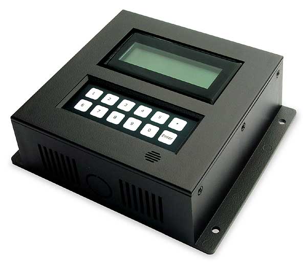
OP6700 Terminal for PIN-Entry
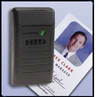
MCAS controllers are compatible with a variety of card-reader types
including barcode, magstripe, and proximity readers. Available card-reader
interfaces include TTL (clock/data), serial (RS-232), and Wiegand (BL1810
only), The image below shows a ProxPoint Plus Proximity Reader (#6008).
This item, made by HID (www.hidcorp.com) is fully compatible with the MCAS.
The following diagram illustrates MCAS connectivity and the ability
to expand the system by adding readers and controllers. The entire
system is controlled by a host PC via a single serial cable. The
RS-485 multi-drop network supports up to 32 MCAS controllers. Reader
controllers are linked together in daisy-chain fashion. The host
accesses an individual controller by its unique board (station) address.
(Note: The diagram below shows a RS-232 link between card-reader
and controller, indicating an ASCII card-reader. )
 The OP6700 controller features Ethernet (TCP/IP) connectivity in addition
to RS-485 multi-drop.
The OP6700 controller features Ethernet (TCP/IP) connectivity in addition
to RS-485 multi-drop.
-
System Requirements
MCAS software requires a Windows laptop or desktop PC with the following
minimum capabilities:
-
Pentium CPU
-
8 MB RAM
-
1 MB Available Hard Disk Space
-
VGA Monitor
-
RS-232 serial port (if applicable)
-
RS-485 converter (if applicable)
-
Ethernet port (if applicable)
-
Windows 98/2000/XP/Vista
Card-Reader Compatibility
MCAS accepts magstripe and proximity card-readers. The following
list contains readers that are known to work with MCAS. Other readers
are also possible:
MagTek Single-Track (2) TTL Reader (part no.21050002)
MagTek Dual-Track (1,2) TTL Reader (part no.21050004)
MagTek RS-232 Reader (part no. 21040071)
HID ProxPoint Plus (6008B), compatible with HID 1326 ProxCard-II cards
HID EntryProx w/keypad (4045CGNU0), Wiegand mode, BL1810 only
Typical magstripe card-reader specification:
Card speed: 3 to 50 ips (7.6 to 127 cm/sec)
MTBF: 1,000,000 passes
TTL (clock/data), Wiegand, or RS-232 card-reader interfaces may
be used with the MCAS card-reader controller. With There is no special
setup or intialization required for using one reader type or the other.
The controller will automatically detect the reader type being used.
(Refer to the Card Reader Controller
section for pin assignments.) A barcode scanner may also be used.
Note: Field-wiring terminal boards used with BL1810 controllers
now provide 2 setup DIP switches to specify either Wiegand or clock/data.
These switches will be set prior to shipping and should not be adjusted
in the field.
MCAS utilizes numeric data from card-reader track-2, extracting the
first 8 ASCII digits from the track for ID storage and comparison.
When using a barcode scanner, a string of numeric digits is extracted from
the device. Most barcode devices also append a carriage-return and/or
linefeed character terminator. The terminator is ignored by MCAS.
Features
MCAS features include the following:
Door/gate access-activation
Configurable activation timer keeps door/gate open for specified
time period
RS-485 host comm. supports distances of 1000 feet or more to the controller
Optional RS-232 host communication instead of RS-485 (BL1810 only)
Ethernet (TCP/IP) support for even greater flexibility
Supports barcode, magstripe, and proximity card readers
Accepts standard track-2 magstripe cards
Uniquely addressable
Onboard battery-backed database maintains user access even if host link
is lost
Firmware supports 20+ host PC commands
Add, modify, and delete users
Card-access logging
Date-based processing for removing expired user records
Photo-based enrollment and identification
Automatic upload for date-based expiration & compatibility with external
databases
Department-based user uploads
Windows PC software for command and control
Compact size (BL1810): controller board measures (3.5" x 2.5") - (available
from the manufacturer)
Field wiring terminal board (FWTB) also available (BL1810)
Keypad, LCD display (OP6700)
Expandable up to 32 reader controllers (RS-485)
Supports up to 1000 users (BL1810) or 250 uses (OP6700)
Configurable activation parameters including "door open" delay
Commerical off-the-shelf controller hardware
In-house firmware programming
"Open door" digital input for easy exit
MCAS software is purchased is licensed in one of 3 available
editions: Lite, Standard, and Premium. The following chart
compares the editions:
|
Feature
|
Lite |
Standard |
Premium |
| Serial communication including
RS-232 & RS-485 |

|
|
|
| Ethernet TCP/IP communication
option |
|
|
|
| Auto-detection of card-reader
controllers |
|
|
|
| Door/gate access-activation
with configurable timer |
|
|
|
| Add, modify, and delete
users |
|
|
|
| PC database supports up
to 1000 users |
|
|
|
| Dynamic card-monitoring
utility |
|
|
|
| Add / configure card-reader
stations |
|
|
|
| Free unlimited e-mail support |
|
|
|
| Card-access
logging - stores access attempts to ASCII formatted log files |
|
|
|
| Date-based
processing - automatically disables expired card users |
|
|
|
| Automatic upload for date-based
processing; also for import of user records from external databases |
|
|
|
| Department-based access
- grants user access to specific readers only: (two available access
levels: single reader & all readers) |
|
|
|
| Photo
enrollment - compatible with digital webcams |
|
|
|
| Automatic
photo identification - displays employee/user photo on card-access attempt |
|
|
|
Ordering
MCAS reader controllers and host software are available at the following
source:
Kenneth Delahoussaye Consulting
web: http://www.kadtronix.com
email: info@kadtronix.com
Installation
Before installing the software, be sure to uninstall any earlier version.
To start the installation process, locate and run the self-extracting
setup file (setup.exe) on the install media. Pay careful attention
to the selection and installation of MCAS hardware. Refer to the Resources
section of this manual for suggested hardware suppliers. Allow only
a qualified technician to perform your MCAS installation.
Where possible, the reader controller should be located in close proximity
with the card-reader (24 inches or less). Ideally, the reader would
be located on an outside wall, while the controller (BL1810) would be installed
behind the wall, out of view and inaccessible to others. If using
the OP6700, mount the device on the wall, close to the card reader.
Place the unit in a location that allows easy access to the keypad and
unrestricted viewing of the LCD display. For RS-485 communication,
MCAS requires a compatible RS485 converter for communicating with card-reader
controller(s) over a RS-485 network. (Converters are available
from a number of suppliers including B&B
Electronics.) Attach the RS-485 converter to an available USB
or RS-232 serial port on your computer. Attach a length of cabling
between the converter and the desired reader controller unit. (Refer
to section 2.5.2 of the BL1800
User's Manual for details concerning RS-485 hook-up.) If using
Ethernet TCP/IP communication, attach appropriate broadband cable to the
RJ45 connector at the controller.
MCAS (BL1810) controllers also offer the option of RS-232 host comm.
instead of RS-485 (default).
When RS-485 host comm.is
active, the RS-232 port (C) may be used with a serial card-reader or barcode
scanner (9600 baud). If RS-232 host comm. is desired, you must tie
PD2
high (+5V). In doing so, RS-485 comm. will be disabled. In
addition, using a RS-232 card-reader will not be possible. RS-232
host comm. rate is 115,200 baud.
For the BL1810, apply a voltage of 7.5VDC to 25VDC at the Vin input.
(Refer to the sample hookup schematic for
details.)
For the OP6700, you may use any available power supply ranging from
9VDC to 40VDC.
For best results, MCAS power should be supplied from an uninterrupable
power source to allow the reader station to continue to operate even if
primary power is temporarily lost.
Ethernet Setup (OP6700 only):
If using the OP6700 with Ethernet, attach the communications cable to
the appropriate port on the back of the unit. Refer to the OP6700
User's Manual for additional details. The unit's network IP address
can be viewed and/or configured by performing the following steps:
Power on the OP6700 device and press the "Enter" key within 3 seconds.
A set of configuration menu choices will appear as shown below:
1 - IP = 10.10.6.100
2 - Net = 255.255.255.0
3 - Port = 3000
4 - Save & Exit
The menu shows 4 configuration options along with the present setting
of each option. Press the "1" key to configure IP address.
After entering the desired address, press the "Enter" key. This will
return you back to the main menu. Press "4" to save the new IP address
to the device's non-volatile memory and exit the configuration menu.
Ethernet Setup (BL1810 only):
The BL1810 does not include Ethernet capability. However, Kadtronix
can apply a special Ethernet option if desired. The field-wiring
terminal board (FWTB) may be adapted with an Ethernet interface including
RJ45 port. Network settings can be viewed and/or configured using
the MCAS host software. Refer to Configure
LAN Devices for details.
Program Operation
Activate the program by selecting:
Start Menu -> All Programs -> Magstripe Card Access System (2.0) ->
Magstripe Card Access System
The user list presents a summary of all users. (Until you have
added new users, the user list display will be blank.) Beneath the
user list are two numeric counter values. The "Users" value indicates
the total number of users. The "Stations" value is the total number
of card-reader stations. These counters update automatically as users
and stations are added or deleted. The edit field near the bottom
section of the display presents status information:
This read-only field typically contains command completion status, network
information, and error details. Just below the status field is a
series of read-only edit fields titled, "TCP/IP:". These controls
will be enabled only if you have selected TCP/IP in your communication
settings. They remain disabled (grayed) otherwise. The
left-most field, indicated "Connection(s)=", denotes the number of active
network connections. A connection can be established only when the
appropriate IP address has been configured
for a controller device. In addition, the IP address must also be
identified in the reader station definition.
The next field, denoted "Pkts:", shows the number of TCP/IP packets which
have been written ("w") and received ("r"). The next control is a
button titled, "...". This button is used to reset your network connections
and may be useful in situations where you have verified network parameters
associated with one or more networked devices, but are unable to establish
a connection.
The "Exit" button terminates the application. If any settings
have been modified, the program will prompt you to save them before termination.
Communication Settings
To access program settings, choose the following from the main menu:
"File -> Settings...". The following dialog will appear on the screen:
First, determine the communications method you will be using: RS-485
multi-drop, RS-232, or Ethernet (TCP/IP). If using RS-485 or RS-232,
select the desired PC communications (COM) port. (If your computer
does not have a serial port, but has USB capability, you may wish to obtain
a USB-to-RS232 adapter.) If you wish to use Ethernet communication,
you must choose the appropriate network port. If you are not sure
what value to assign, simply use the default value shown. Refer to
Ethernet
setup for details on configuring the reader station for network communication.
Use the "Latency" control to specify message delays. The latency
is necessary to accommodate reader(s) that may be a long distance away
from the host PC. This adjustment is used for RS-485 communication
and should be made based on the reader station that is the farthest distance
away. Adjust high for long distances and low for short distances.
Initially adjust to the lowest position. If message errors result
during communication, try using a higher latency.
"Encryption" specifies whether or not messages will be scrambled.
By default, all command and response messages are scrambled as a security
measure.
Adding Reader Stations
One of the first actions to perform is adding card-reader stations.
A reader station is defined as the hardware and equipment associated with
an access entry location. This includes the MCAS controller and the
associated card-reader. An access entry location may be a hallway,
entrance, gate, door, etc. You must define at least one reader station.
To do this, use the main menu (top) and choose "Stations -> Add/Modify...".
The following dialog appears:
At the bottom of the display page is a field titled, "Stations List:".
This region shows a summary of all defined reader stations. This
field will be blank if you have not defined any stations yet. To
define a reader station, you will use the remaining controls featured on
the page.
The "Select:" combo-box control at the top of the page selects a station
index value from the database. To add a new station, user the "Add
New" button. (This will automatically choose the correct index within
the "Select:" combo box.) Next, enter the station ID. This
8-digit field is the board serial number of the MCAS controller.
It may be found printed on a label on the outside of the box or anti-static
bag containing the controller. The station ID allows a specific controller
to be addressed and is required for both RS-485 and Ethernet communications.
Enter this number exactly as shown on the label. Next, enter a text
description of the station. You should make this string something
meaningful that will help you easily identify the location of the station.
Once you have defined the station ID and description, you should choose
the desired activation time. The activation time designates a timed
delay which occurs after a valid card swipe has occurred. This parameter
defines the amount of time (in seconds) that the door/gate remains unlocked.
When unlocked, one of the available the high-power digital outputs is active.
Each of the high-power digital outputs can each sink up to 200 mA at 30V
(BL1810) or 200mA at 40V (OP6700). This option is ideal for driving
relays or solenoids. (Refer to section 2.2.2 of the BL1800
User's Manual or section 3.1.2 of the OP6700
User's Manual for details.) When this method of activation is
used, card-swipe by a valid user results in the digital output becoming
active. The output remains active for the time period specified by
"Activation Time". After this time has elapsed, the output becomes
inactive. (The default digital output signal assignment is made in
the controller firmware. If necessary, the assignment can be changed
via a manual command.)
The Mode field defines the card access mode for the MCAS controller.
There are three selections: Card and PIN, Card Only, and PIN Only.
PIN modes require a keypad. Unless the card reader contains an integrated
keypad, only the Card-Only mode will be allowed. (Note:
Mode may be unused in some MCAS controller firmware revisions.)
The next section of the display
allows you to specify how the reader station responds to received broadcast
commands.
By default, a reader station will not respond to a broadcast command
from the host PC (response latency = "Disabled"). This ensures there
are no collisions due to multipe reader stations attempting to respond
simultaneously. However, there may be times when broadcast responses
are desireable. For instance, you may wish to poll all reader stations
for system status or card-swipe history. Rather than issuing individual
commands to each reader, you could issue a single broadcast command and
await responses from all reader station(s). However, you must use
caution when implementing broadcast commands/responses. It is imperative
that you apply proper broadcast response latency values to each reader
station. (Note: Be careful not to confuse broadcast response
latency with the communications latency described in the settings
section.) The response latency value provides a method of avoiding
message collisions. It tells the reader station how long to delay
(in milliseconds) before attempting to issue a response to a broadcast
command. For example, consider a network of 5 reader stations interfaced
to a common host via RS-485 bus. If the user desires to implement
broadcast messaging, he might enter the following response latencies:
Reader
Station
ID
|
Broadcast
Response
Latency (mS)
|
|
00721205
|
0
|
|
00515333
|
50
|
|
01003411
|
100
|
|
00212334
|
150
|
|
00425221
|
200
|
The latency values you choose will depend on number of factors including
the number of reader stations and the distances away from the host PC.
By staggering the response messages, you avoid message collisions.
If you have specified Ethernet communication instead of RS-485, then
you must provide the network IP address associated with the reader station.
Each reader station must be configured with a unique IP address.
(Ethernet communication is applicable only to devices having this capability
such as the OP6700.) Refer to sections describing Ethernet
setup and communications settings
for additional details. (Note: A valid 8-digit reader station
ID is also required when using Ethenet communication.)
Static IP addressing is required by MCAS host software to allow it to
properly locate and identify MCAS controller(s).
(Note: For proper communication, both an Ethernet (IP) address
and
station ID must be specified. To program an IP address at the device,
use the LAN configuration tool.
If necessary, you may use auto-detection
to identify a controller's station ID.)
When you have completed assignment of the reader station fields, click
"OK" to save them and return to the main dialog display. Now that
you have added or modified a station entry, you must update the changes
to the reader station(s). Do this by selecting:
"Stations->Upload..."
The following message appears:
Choose "All" to update all card-reader stations individually.
Alternatively, you can select "Single" to update one station only.
For this selection, use the combo-box drop-list to choose the desired station.
(Note: If you have specified Ethernet communication, the
MCAS host application will attempt to establish network connection(s) with
the controller(s). Once connected, the software will issue periodic
"ping" messages. Each controller must respond to these messages in
order to keep the network connection alive. If the station ID has
not been properly set up within the MCAS host application, the controller
will not respond to the ping message and the network connection will be
dropped. The MCAS host application will subsequently re-establish
the connection, but then terminate the link once again if the controller
does not respond. Henceforth, your system will continually establish
a connection and then lose the connection. To remedy this condition,
you must provide the proper station ID associated with the controller as
indicated above.)
Adding Users
Each user should be assigned an identification card (track-2 standard)
with a unique ID number. The card may be a driver's license, credit
card, or custom-designed card such as the one shown below:
(Note: If the card designates more than 8 numeric digits, then
use only the upper digits. For instance, consider the following fictitious
credit card number:
0082
1288 7890 3456
To use this credit card number as your ID, extract the upper 8 digits
as shown:
00821288
To add or change a user, click the "Add/Modify..." button. Alternative,
you may select "Users -> Add/Modify" from the file menu.
The following dialog will appear:
To add a new user, click "Add New". Enter the first and last names
of the user being added. Also enter the user's card ID. (This
field should be an 8-digit numeric value.) For PIN-entry systems
including the OP6700, enter a 4-digit personal identification number (PIN).
This number should be kept secret by the user. It will be entered
by the user at the keypad after a successful card-swipe. (PINs are
not used in BL1810 controllers.) To add another user, click
"Add New" once again and enter his information following the same procedure
as before. The index field (upper left) is a drop-down
combo control for accessing a user entry. (Optionally, you may use
the convenience buttons, "<<" or ">>" to quickly locate user records.)
After selecting the desired user entry, you may modify or delete it.
The "Date Activated:" field indicates when the specified user record was
defined and added to the database.
Use "Reader Station Access:" if you want
to define department-based user records. This feature allows you
to define which department or site is valid for the particular employee
or user. Choose "ALL" if the user is allowed to access all stations.
(This feature is available only in MCAS Standard and Premium editions.)
The check-box titled, "Photo enrollment"
is used to activate photo-based enrollment and identification. (Optionally,
you may also use this menu option: "Users -> Enable Photo ID / Enroll...".)
Available in the MCAS Premium edition only, this feature is useful for
security and provides quick identification of users entering access-controlled
areas. When properly activated and configured, an employee or user
photo is automatically displayed when his card is swiped at a reader station.
When the "Photo enrollment" check-box is enabled, the following dialog
appears:
Begin by defining the user fields (name,
card ID, PIN, etc.) as desribed above. To specify a photo, you may
import an existing bitmap image or capture a photo using a compatible web-camera
such as the Logitech Quickcam. Once a photo is selected for a specified
user, the image will be saved and displayed as shown below:
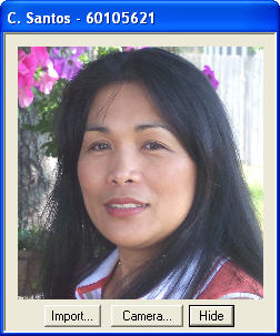
You may use the "Hide" button to extinguish the dialog. Or, specify
another user record and photo as previously described.
(Note: For proper operation of photo-based identification, it
is necessary to ensure that remote reader stations have the correct date/time.
The time at the readers must match the date/time at the host PC.
See Set Station Date / Time for additional
details.)
The "Access Period" is used for date-based expiration and defines the
time period (in days) that user access will be permited. If you specify
"Unlimited", the user will be allowed system access indefinitely (or until
deleted from the database). If "Limited" is selected, the user will
be allowed access privileges up to (and including) the indicated termination
date. After this date, the user will be denied access at the reader
station(s). Date-based expiration is available only in standard and
premium editions.
(Note: If you plan to use date-based expiration as describe above,
then auto-upload processing must be
active for proper handling of expired user records.)
When you have finished adding user(s), click "OK". (Or click "Cancel"
if you do not wish to store any of the user(s) you've just added.)
The following dialog will appear:
At this time, you must update your changes to the card reader station(s).
Select the reader station(s) you want to update. Choose "Single"
to update a single reader station only. In most instances, you'll
want to update all stations by selecting "All".
Saving
After making changes such as adding/modifying users or reader stations,
you may save the database to a file on your PC. Do this by selecting:
"File -> Save..."
The following message appears:
Click "Yes" to save your changes. (Note: MCAS software versions
2.1.5 and later have an auto-save feature which periodically checks for
modified settings and automatically saves them to your computer's hard
disk.)
Manual Commands
In most cases you will not have a need to use manual commands.
It is available for advanced users and is a useful for trouble-shooting
and testing. To perform a manual command, click the "Manual Commands"
check box near the bottom of the main dialog. You may manually type
a command string and send it to card-reader station(s). Valid commands
are listed in the MCAS Programmer's API
section of this manual.

Once you have entered the desired command, click the "Send" button.
Specify the desired reader destination(s) using the dialog window below:
Choose "Single" to issue the request to a single reader station only.
In some instances, you'll want to send to all stations by selecting "All".
(Caution: Manual commands should be attempted only by advanced users
and are not recommended for the novice.)
Enabling Stations
This option enables or disables one or more card reader stations.
This is useful for globally denying access entry to all users at one or
more sites and could be useful in situations where safety and/or security
are in question.
To enable one or more stations, choose the following menu option:
"Stations->Enable"
To disable one or more stations:
"Stations->Disable"
By default, stations are enabled.
Tools
MCAS provides the following tool selections. They are available
from the "Tools" menu:
Poll Stations
This option issues a presence request to one or more specified reader
stations and provides a quick means of determining if a station is responding.
(Note: This option can be applied for known stations. If stations
are unknown, use the Auto-Detect Stations menu option.)
Auto-Detect Stations
When active reader station addresses are unknown, you may use this
option to detect and display them. A detection request message is
broadcast to all readers. To minimize the liklihood of RS-485 message
collisions, a maximum response latency value is provided. This value
allows each reader station to compute a random response latency, allowing
each station to respond at different times during the max. latency period.
Choose a maximum response latency appropriate for the number of active
reader stations. The higher the value, the smaller the chance of
collision(s). (Note: Auto-detect response latency should not
be confused with broadcast response latency.)
To use this feature, select the following from the menu:
"Tools->Auto-Detect Stations..."
Open Door/Gate
The option provides a means of remotely activating access at one or
more stations as if a valid card-swipe had occurred. This feaure
is useful for granting entry to vendors, repair technicians, or others
who may need one-time access, but who do not have a magstripe ID card.
When the command is issued, the door or gate will be unlocked for the time
period specified by station parameters and will then automatically return
to the locked state.
Clear Card-Access History
This option erases the card-swipe history. This data is a list
maintained within the MCAS controller hardware that contains card-swipe
IDs from the most recent access attempts. (Note: Card-swipe
data is stored regardless of the card's validity. That is, the data
is stored even if the card ID does not exist in the local MCAS database.)
Configure Auto-Upload
This option allows you to configure a schedule for automatically uploading
database user records to remote controllers. When enabled, uploads
occur automatically at the prescribed time each day. (You must enable
this option if date-based expiration of user records is needed.)
To configure auto-upload, selec the following menu item:
"Tools->Configure Auto-Upload..."
Configure LAN Devices (BL1810
only)
This option is applicable only to BL1810 controllers. Although
the BL1810 does not provide Ethernet capability, Kadtronix can apply a
special add-on option enabling TCP/IP connectivity. Adapted controllers
must be configured with static IP addressing for proper communication.
Before using this utility, ensure that your Ethernet-enabled controller
is powered on and comm. cable has been plugged in. To run the utility,
select the following from the menu:
"Tools->Configure LAN devices..."
When invoked, the utility activates a detection sequence, searching
for active devices. When complete, the dialog lists detected devices
available for configuration. (Note: Until LAN-enabled device
has been properly configured, use a direct connection where possible.
To facilitate proper detection, avoid using a gateway device or router
until after the configuration has been completed.)
The dialog is divided into two sections, labelled "Configure" and "Describe".
The configure section provides fields for specifying network parameters.
The following fields must be specified for proper network communication
of Ethernet-enabled controllers:
-
IP address (static)
-
Subnet
-
Gateway (or router)
-
Port No.
(Note: Remaining fields in the configure section are provided
for information only and do not require any changes.) To view the
settings associated with a device, left-click a selection in the list.
Choose the proper settings based on your network. (Note:
Port number assignment must match the value specified in MCAS
settings.) Once you have specified the desired settings, left-click
the "Apply" button to store and implement them at the remote controller.
After the utility completes the configuration, it will automatically initiate
a new detection sequence and list the updated parameters. (You may
initiate a detection any time by left-clicking the "Detect" button.)
The "Describe" section is optional and allows you to provide descriptions
for your LAN-enabled controller. This feature is helpful where multiple
controllers exist on the network and allows you an easy way of describing
each node. Populate the following fields:
-
MAC address
-
Device Description
You may manually enter the 12-digit MAC address or you can populate
it by transferring from the configuration list located left using the "To->"
button. Type a descriptive name or phrase to help you remember the
node's purpose and/or location. Then, left-click "Add/Replace" to
add the new description. To remove a description, select it, then
left-click "Delete".
Once you have completed your changes, left-click the "OK" button to
save and exit.
Monitor Card-Access
To use this tool, select the following from the menu:
"Tools->Monitor Card-Access"
This option retrieves, displays, and logs real-time data containing
card-access attempts at reader station(s). It also provides
timestamps indicating the date/time the card-access attempt occurred at
the reader station. The application issues periodic broadcast commands
to all readers, requesting card-swipe history. (Note:
This tool utililizes broadcast messaging and requires that each reader
station is configured with the proper broadcast
response latency. Improper configuration could result in
missing responses and/or message collisions (RS-485 only).)
This function is required if you desire to store and view log files.
Remote reader stations tempoarily store card-swipe history data until it
is requested by the host computer. (Note: Since reader
stations have limited memory storage, you should execute the Monitor Access
periodically to capture/store the records and prevent the loss of data
due to buffer overrun at the reader stations.)
To capture card-access data, first enable the check-box titled, "Save
log files". (Note: File logging can consume a large amount
of disk space over time. If file logging is not necessary for your
application, you should leave this check-box empty.) Next, activate
data retrieval & monitoring using the "Start" button. This will
perform periodic uploads from all reader stations and store the data to
log files (if enabled). The retrieval & monitoring operation
will also enable the "View Logs..." button, allowing you to view
log files which have been stored to your computer.
If you are using RS-232 host communication instead of RS-485 or Ethernet,
you should enable the check-box titled: "RS232 Host Comm.". This
will disable broadcast command polling and allow unsolicited received card-swipe
messages instead.
If the reader station(s) have not been configured for broadcast
response latency, you may do so using the "Configure" section as shown
below. To enable response latency, choose the reader station and
enter the desired latency value. Then, click the "Upload" button.
The "Detections" field lists real-time card-swipe access attempts.
Each record contains timestamp, card-ID, and reader station address
for each access attempt. (Note: A detection record may also
have the following appended sub-string indicator: <!>.
This string, when present, indicates the card ID was not found in the controller's
local database and represents an unknown card-swipe attempt.)
You may select the desired broadcast command rate from 300 to 5000 milliseconds.
The faster the rate, the more quickly card data is retrieved. However,
if there are multiple readers on the bus, you must allow time for them
all to respond based upon their user-defined broadcast
response latencies.
The field at the bottom of the display shows received, unprocessed data
characters from reader station(s). It is this data which is used
to extract card-access data displayed in the "Detections" region above.
View Access Logs
This option allows you to view stored card-access log data which has
been stored to your computer's hard disk drive. Log files are created
and stored when you enable logging using the "Enable Card-Access Logging"
menu selection. Logging can also be enabled & viewed using
the Monitor Card Access feature.
(Card-access logging is available in MCAS Standard and Premium editions
only.) To view card-access logs, use the fpllowing menu item:
"Tools->View Card-Access Logs...". .
The large list control within the display is the viewer field and shows
card-access log records of interest. Over time, log files can grow
quite large, making it difficult to locate and view specific records of
interest. The combo controls provided at the top of the display allow
you to filter the data so you can more easily find the desired information.
The "Terminal:" control allows you to choose the reader station(s) and
is useful if you have defined department-based
users. Choose "All" otherwise.
The "Period Begin:" and "Period End:" controls select the desired date
range. Only card-access attempts which have occurred within this
range will be displayed in the viewer field.
Use the "Refresh" button at the bottom of the display to refresh the
viewer field. This is useful in the event that new data has been
recently stored. If desired, use the "Auto-refresh" check-box to
automatically refresh the display on a periodic basis.
Check the box titled, "24-hour time" to display time entries in
military format. If unchecked, time will be displayed in standard,
12-hour format with AM/PM indicators.
Log files are stored in ASCII text format and can be viewed using any
compatible text editor or viewer. These files can be found at the
following folder location:
C:\Program Files\Magstripe Card Access System 2.0\Data\erpts
The files are named with the following convention:
_nnnnnnnn.txt
The designator, "nnnnnnnn" indicates an 8-digit numeric card-ID.
Set Station Date / Time
This option is used to configure the date and time at card reader station(s).
Each station controller has a built-in realtime clock that is used primarily
for time-stamping card-access transactions. To set date/time select
the following menu item:
"Tools->Set Station Date / Time..."
The following dialog window will be displayed:
Verify that the date and time listed match the computer's system's clock.
(Note: It is imperative that reader station(s) are closely syncronized
with the host PC.) Left-click the "OK" button to issue the update
request to reader station(s).
License Registration
Registration is required prior to receiving product support. It is
also required when requesting software edition upgrades. Registered
users who request such upgrades will receive a registration license key-code
by e-mail. The license key is required for activating edition-specific
features. (MCAS Lite edition does not require a license key.)
To register, select the following application main menu item:
"Help -> Registration..."
When the "Register" dialog appears, fill in the requested information
as shown in the example above. When complete, click "Send" to transmit
the information to Kadtronix. (A valid e-mail account and internet
connection are required to perform this operation.)
After you have received a license key from Kadtronix, select the following
main menu item:
"Help -> Enter License Key..."
Enter the encoded key string as shown in the example below. Click
"OK" to accept the new key and enable the edition upgrade.
Card Reader Controller
The controller provides the interface between the card-reader and the
host PC. This intelligent device accepts control commands from the
PC for adding and removing users. It maintains a stand-alone database
of all users in battery-backed SRAM and is capable of functioning even
if the communications link is temporarily lost. Manufactured by Z-World,
the BL1810 single-board
computer is the basis of the controller and contains onboard processor,
memory, I/O, and drivers to support MCAS operation. Measuring only
3.5" x 2.5", the controller can be mounted in almost any space. Kadtronix-supplied
field-wiring terminal board (FWTB) is available for the BL1810 and provides
the following features:
-
Easy screw-terminal wiring connections
-
Onboard door/gate control relay
-
Activity LED indicator
Optionally, you may choose an integrated solution consisting of 12-key
keypad, 4x20 LCD display with backlight, and Ethernet communication.
The OP6700 is also
available from Z-World and can be
easily attached to any wall or suitable surface.
Sample Hookup Schematic (BL1810)
The following schematic diagram shows a typical MCAS (BL1810) hook-up
scenario:
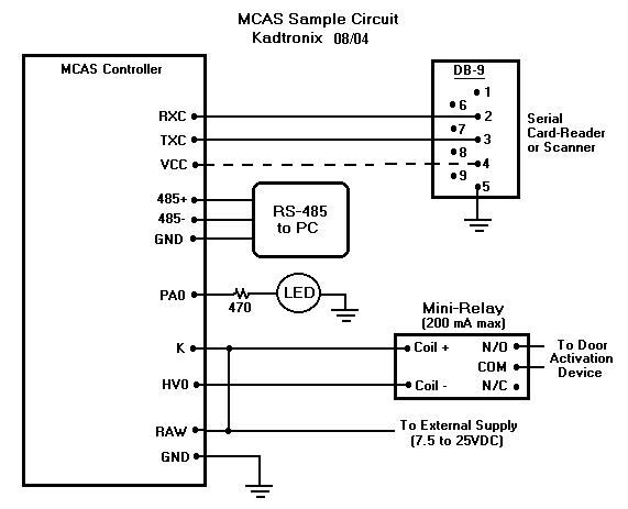
Note 1: Also required (not shown in the diagram above)
are pulldown resistors at MCAS controller signals PD0 (J5-19), PD1 (J5-20),
and PD2 (J5-21). Refer to the pin-out signal
descriptions for details.
Note 2: The diagram above indicates a RS-232 card-reader.
A TTL (clock/data) reader, proximity reader, or barcode scanner may
also be used. Refer to the pin-out signal descriptions
for details. The dashed line indicates a port-powered connection
where the reader device obtains its power from the serial port.
MCAS is compatible with RS-232, clock/data, and Wiegand readers as listed
in the following wiring guides:
BL1810 Card-Reader Wiring
Magstripe RS-232 Reader
MagTek #21040075
Reader
Signal
|
Wire
Color
|
Notes
|
BL1810
Connection
|
|
TX (2)
|
Yellow
|
|
RXC [J5-4]
|
|
RX (3)
|
Green
|
|
TXC [J5-6]
|
|
PWR (4)
|
Orange
|
|
VCC [J5-1]
|
|
GND (5)
|
Brown
|
|
Ground [J5-2]
|
BL1810 Card-Reader Wiring
Proximity, Wiegand
HID EntryProx #4045CGNU0 (w/keypad)
Reader
Signal
|
Port/Wire
Color
|
Notes
|
FWTB
Terminal
|
Wieg.
Data 0
|
P3 / Grn
|
1
|
T-5
|
Wieg.
Data 1
|
P3 / Wht
|
1
|
T-6
|
|
PWR
|
P1 / Red
|
|
T-2
|
|
GND
|
P1 / Blk
|
|
T-8
|
|
|
|
|
| Note 1: The reader must be keypad-programmed for
Wiegand output mode. Kadtrpnix can perform this programming for a
small fee. |
OP6700 Card-Reader Wiring
MagTek #21040075
Reader
Signal
|
Wire
Color
|
Notes
|
OP6700
Connection
|
|
TX (2)
|
Yellow
|
|
RXC [J7-7]
|
|
RX (3)
|
Green
|
|
TXC [J7-6]
|
|
PWR (4)
|
Orange
|
1, 2
|
-
|
|
GND (5)
|
Brown
|
|
Ground [J7-2]
|
| |
|
|
|
| Note 1: Since the OP6700 does not provide +5VDC
output, an external voltage supply or regulator is required. |
| Note 2: Use 220-ohm resistor in series between
VCC and card-reader power input. |
BL1810 Card-Reader Wiring
Magstripe, TTL Reader
MagTek #21050002
Reader
Signal
|
Wire
Color
|
Notes
|
FWTB
Terminal
|
|
Clock
|
Grn
|
|
T-5
|
|
Data
|
Yel
|
|
T-6
|
|
Card Pres.
|
Ora
|
|
T-4
|
|
PWR
|
Red
|
|
T-3
|
|
GND
|
Brn
|
|
T-8
|
|
BL1810 Card-Reader Wiring
Magstripe, TTL Reader
MagTek #21040025
Reader
Signal
|
Wire
Color
|
Notes
|
FWTB
Terminal
|
|
Clock
|
Grn
|
|
T-5
|
|
Data
|
Brn
|
|
T-6
|
|
Card Pres.
|
Wht
|
|
T-4
|
|
PWR
|
Red
|
|
T-3
|
|
GND
|
Blk
|
|
T-8
|
|
OP6700 Card-Reader Wiring
MagTek #21040025
Reader
Signal
|
Wire
Color
|
Notes
|
OP6700
Connection
|
|
Card Pres.
|
White
|
|
IN2 [J7-10]
|
|
Data
|
Brown
|
2
|
IN1 [J7-9]
|
|
Strobe
|
Green
|
2
|
IN0 [J7-8]
|
|
Vcc
|
Red
|
1
|
-
|
|
Gnd
|
Black
|
|
GND [J7-5]
|
| |
|
|
|
| Note 1: Since the OP6700 does not provide +5VDC
output, an external voltage supply or regulator is required. |
| Note 2: For proper operation of TTL card-readers,
resistors R63 and R65 must be shorted or replaced with 0-ohm resistor.
This
operation should be performed by a qualified technician with proper soldering
experience. |
BL1810 Card-Reader Wiring
Proximity, TTL Reader
HID ProxPoint Plus #6008B
Reader
Signal
|
Wire
Color
|
Notes
|
FWTB
Terminal
|
|
Clock
|
Wht
|
|
T-5
|
|
Data
|
Grn
|
|
T-6
|
|
Card Pres.
|
Vio
|
|
T-4
|
|
Beeper
|
Yel
|
1
|
T-7
|
|
PWR
|
Red
|
|
T-3
|
|
GND
|
Blk
|
|
T-8
|
|
|
|
|
| Note 1: Optional connection |
Pin-Outs
The following table lists the pin-outs and descriptions for MCAS 1810
board connectors. Note that only a subset of the pins will be used
in any given application. Refer to the sample
hookup diagram for more information.
MCAS (BL1810)
Controller Pin Assignments
|
Connector
|
Pin(s)
|
BL1810
Function
|
MCAS
Description
|
|
J1
|
2
|
Vin
(Raw)
|
Input
Supply Voltage ( 7.5 25Vdc ) |
|
J4
|
38
|
Vin
(Raw)
|
Input
Supply Voltage ( 7.5 25Vdc ) |
|
J1
|
1,3
|
Ground
|
Ground |
|
J4
|
1,11,12,23,32,39
|
Ground
|
Ground |
|
J5
|
2,27,28,37,40
|
Ground
|
Ground |
|
J5
|
1,31,32
|
VCC
|
Regulated
+5VDC output |
|
J4
|
2,40
|
VCC
|
Regulated
+5VDC output |
|
J4
|
37
|
K
|
Voltage
supply for high-power digital output drivers HV0, HV1, HV2, and HV3.
(Required for door-activation device [e.g., relay].) Can be connected
to VCC or Vin. (30V Max.) |
|
J4
|
3
|
PA0
|
System
Status: digital pulse output indicates board is operational. Can
be tied to a LED. |
|
J4
|
4
|
PA1
|
Access
Status: digital pulse output. HIGH = indicates successful card-swipe
access; LOW = normal, idle state. Can be tied to a LED. |
|
J4
|
13
|
PB0
|
^CLD:
card-presence digital input, active-low (for magstripe & proximity
TTL card readers) |
|
J4
|
14
|
PB1
|
^CLD1:
card-presence digital input, active-low: optional, for insert-readers
only: (for magstripe TTL card reader) |
|
J4
|
15
|
PB2
|
^RCL:
Track-2 clock digital input, active low (for magstripe & proximity
TTL card readers) |
|
J4
|
16
|
PB3
|
^RDTL:
Track-2 data digital input, active low (for magstripe & proximity
TTL card readers) |
|
J4
|
19
|
PB6
|
Beeper:
Optional connection on TTL proximity card-readers for beeper host control. |
|
J4
|
33
|
HV0
|
High
power digital (sinking) output, 200 mA; used for access activation of door/gate.
(Default) |
|
J4
|
34
|
HV1
|
High
power digital (sinking) output, 200 mA; used for access activation of door/gate. |
|
J5
|
19
|
PD0
|
Reserved
(See note 3 below.) |
|
J5
|
20
|
PD1
|
Door
exit button digital input (optional), active high.
(See
note 3 below.) |
|
J5
|
21
|
PD2
|
Host
comm. select: LOW=>RS-485 (default), HIGH=>RS-232 (port C).
This signal is sampled only on power-up/reset. (See notes 3,4 below.) |
|
J5
|
3
|
RXB
|
Serial
receive signal for successful card-swipe RS-232 activation (optional).
Also functions as optional card-reader port when host comm. is RS232 (see
PD2 above). |
|
J5
|
5
|
TXB
|
Serial
transmit signal for successful card-swipe RS-232 activation (optional).
Also functions as optional card-reader port when host comm. is RS232 (see
PD2 above). |
|
J5
|
4
|
RXC
|
Serial
receive signal for RS-232 host comm., card-reader or barcode scanner.
(See notes 1,4 below.) |
|
J5
|
6
|
TXC
|
Serial
transmit signal for RS-232 host comm., card-reader or barcode scanner.
(See notes 1,4 below.) |
|
J5
|
29
|
RS485-
|
Serial
RS-485 signal for host PC command and control. (See note 4 below.) |
|
J5
|
30
|
RS485+
|
Serial
RS-485 signal for host PC command and control. (See note 4 below.) |
|
|
|
|
| Note 1:
Some serial card-readers require power via the DTR signal of its serial
communications cable. To accomplish this, connect the DTR signal
(pin 4 of the reader's 9-pin D-connector) to +5V (Vcc). |
| Note
2: The BL1810 offers additional signals which may be useful for custom
applications. Consult Kadtronix for details. Also refer to
the ZWorld user's manual (HTML
/ PDF)
for details. |
| Note
3: Pull-down resistor is recommended (e.g., 15K-ohms). |
| Note
4: RS-485 is the default host comm. protocol. When RS-485 host
comm. is active, the RS-232 port (C) may be used with a serial card-reader
or barcode scanner (9600 baud). If RS-232 host comm. is desired,
you must tie PD2 high (+5V). In doing so, RS-485 comm. will be disabled.
In addition, using a RS-232 card-reader will not be possible. RS-232
host comm. rate is 115,200 baud. |
MCAS (BL1810)
Field Wiring Terminal Board (FWTB)
Screw-Terminal
Assignments
|
Terminal
|
Name
|
Notes
|
Description
|
|
1
|
GND
|
|
Ground |
|
2
|
PWR
|
|
Input power (+12VDC recommended) |
|
3
|
Vcc Out
|
|
+5VDC out (100mA max) |
|
4
|
^CLD
|
|
Card presence |
|
5
|
^RCL
|
|
Strobe or Data0 (Wiegand) |
|
6
|
^RDTL
|
|
Data
or Data1 (Wiegand) |
|
7
|
Beeper
|
|
Beeper
digital output, optional (proximity readers) |
|
8
|
GND
|
|
Ground |
|
9
|
Cnt. 1
|
|
Door/gate
activation relay contact (COM) |
|
10
|
Cnt. 2
|
|
Door/gate
activation relay contact (N/O) |
|
11
|
Tx-R
|
|
Transmit
signal output (RS-232 card-reader, 9600 baud) |
|
12
|
Rx-R
|
|
Receive signal input
(RS-232 card-reader, 9600 baud) |
|
13
|
Exit
|
|
Door-exit button digital
input (active-high) |
|
14
|
Tx-H
|
|
Transmit signal output
(RS-232 host comm., 115K baud) |
|
15
|
Rx-H
|
|
Receive signal input
(RS-232 host comm., 115K baud) |
|
16
|
GND
|
|
Ground |
|
MCAS (OP6700)
Screw-Terminal Assignments
J7
Terminal
|
Name
|
Notes
|
Description
|
|
1
|
PWR
|
|
Input power (+9 to 40VDC) |
|
2
|
GND
|
|
Ground |
|
3
|
485+
|
|
RS-485(+) for multi-drop
communication. |
|
4
|
485-
|
|
RS-485(-) for multi-drop
communication. |
|
5
|
GND
|
|
Ground |
|
6
|
TXC
|
|
Serial
transmit signal for RS-232 card-reader or barcode scanner. (See note
3 below.) |
|
7
|
RXC
|
|
Serial
receive signal for RS-232 card-reader or barcode scanner. (See note
3 below.) |
|
8
|
IN0
|
2
|
Track-2
clock digital input, active low (for magstripe & proximity TTL
card readers) |
|
9
|
IN1
|
2
|
Track-2
data digital input, active low (for magstripe & proximity TTL
card readers) |
|
10
|
IN2
|
|
^CLD:
card-presence digital input, active-low (for magstripe & proximity
TTL card readers) |
|
11
|
IN3
|
|
Door
exit button digital input (optional), active low |
|
12
|
OUT0
|
|
Door lock/unlock activation,
open collector, sinks 200mA @ 40VDC |
|
13
|
OUT1
|
|
N/C |
|
14
|
OUT2
|
|
N/C |
|
15
|
OUT3
|
|
N/C |
| |
|
|
|
| Note 1:
Many card-readers require an external +5VDC power source. This can
be provided using a standard voltage regulator such as the 7805.
If desired, the regulator can be affixed to the inside of the OP6700 enclosure.
(Be careful to mount the regulator in such a way as to avoid short-circuiting
other components.) Choose a suiltable location (preferrably the floor
of the OP6700 enclosure). Carefully drill a small hole for attaching
the regulator. Secure with screw, nut, and lock-washer. Wires
must be soldered to each of the 3 legs: input, output, and ground. This
operation should be attempted only by a qualified electronics technician
with proper soldering and assembly experience. |
| Note 2:
For proper operation of TTL card-readers, resistors R63 and R65 must be
shorted or replaced with 0-ohm resistor. This operation should
be performed by a qualified technician with proper soldering experience. |
| Note 3:
Some serial card-readers require power via the DTR signal of its serial
communications cable. To accomplish this, connect the DTR signal
(pin 4 of the reader's 9-pin D-connector) to your externally provided
+5VDC power source. |
Connecting a Power Supply
To activate the MCAS (BL1810) controller, apply a voltage of 7.5VDC
to 25VDC to the Vin input (refer to the pin-out table above). Vin
is available on connector J4 as well as J1. The controller provides
a regulated DC output of 5 volts. You may use this supply for powering
external devices, but keep current draw to a minium to prevent damage to
the regulator.
To activate the MCAS (OP6700) device, apply a voltage of 9VDC to 40VDC
to the PWR input, screw terminal J7-1. Since the OP6700 does not
provide a regulated output for powering external devices such as card-readers,
an external source of 5VDC must be provided such as 7805 regulator.
The following table shows the wiring plan:
+5V
(7805) Voltage Regulator
Wiring Plan for
OP6700
Regulator
Pin
|
J7
Terminal
|
Description
|
|
1
|
1 (PWR)
|
+Vraw (regulator
input)
|
|
2
|
2 (Gnd)
|
Ground
|
|
3
|
-
|
+5VDC out
|
| |
|
|
| Note 1:
Pin 1 is the left-most pin when viewing the front of the 7805 device package. |
Connecting a Door
Activation Device
If you wish to use MCAS to electronically control access to a door
or gate, the proper connection must be made to your electric door strike
or other door actication device. However, the MCAS controller is
not capable of supplying the power required to directly operate such a
device. Instead, a low-power relay should be used (100mA or less
recommended). Connect one side of the relay coil to BL1810 signal
HV0 [pin J4-33]. HV0 provides the ground path and can sink up to
200mA. Connect the other relay coil signal to the desired supply
voltage. Please note that BL1810 signal line K (J4-37) must also
be connected to the supply. K can be any voltage up to 30V.
If using a 5V relay, K may be tied to VCC. Just remember to connect
K to the supply you want to use for controlling the relay.
(Note: If using the FWTB, refer to screw-terminal assignments
in the appropriate table above.)
If using the OP6700, connect one side of the relay coil to OUT0 [J7-12].
OUT0 provides the ground path and can sink up to 200mA @ 40VDC. Connect
the other relay coil signal to the supply (PWR) voltage [J7-1].
Connecting a Door Exit
Button
An optional door-exit button may be used with MCAS. A door-exit
button provides the means to activate a door or gate from inside the access
area, without the need to swipe a card. Pressing the switch results
in door/gate activation as if a valid card swipe and PIN entry had occurred.
Any suitable single-pole, normally open, momentary contact switch may be
used.
If using the BL1810, the door-exit signal is active-high. Attach
one switch terminal to PD1 [J5-20]. Attach the remaining switch terminal
to VCC. Solder a 15K-ohm pull-down resistor between PD1 and ground.
(Note: If using the FWTB, refer to screw-terminal assignments in
the appropriate table above.)
If using the OP6700, the door-exit signal is active-low. Attach
one switch terminal to IN3 [J7-11]. Attach the remaining switch terminal
to ground.
Enabling RS-232
Host Communication (BL1810 only)
RS-485 is the default host comm. protocol.
When RS-485 host comm. is active, the RS-232 port (C) may be used with
a serial card-reader or barcode scanner (9600 baud). If RS-232 host
comm. is desired, you must tie MCAS controller pin PD2 high (+5V).
Otherwise, solder a 15K-ohm pull-down resistor between PD2 and ground
for RS-485. RS-232 host comm. rate is 115,200
baud. Refer to the pin-out signal descriptions
for additional details.
-
Firmware Upgrades
The MCAS host software includes a field upgrade utility developed by
Z-World.
In special situations, Kadtronix may provide you with a firmware
upgrade for the purpose of correcting a problem or providing new features.
The upgrade will be provided in the form of a binary file. To perform
the upgrade, you will need a programming cable from Z-World.
The diagram below shows the hookup configuration:
Before beginning, power down the MCAS controller and attach one end
of the programming cable to the host PC. Attach the other end
to the MCAS controller board at connector J3, aligning the red stripe of
the ribbon cable with pin 1 on the connector (indicated by a small white
dot). Apply power to the MCAS controller and then activate the upgrade
utility program by selecting:
Start Menu -> Programs -> Magstripe Card Access System (MCAS) -> Firmware
Upgrade
Select the communications parameters by selecting::
"Setup -> Communications..."
Choose a baud rate of 115200 and the required comm port. Then,
select the binary image file by selecting:
"File -> Load Flash Image..."
Use the browse ("...") button to navigate to the folder containing the
binary image file. Select "OK" to load the firmware. When complete,
remove power from the MCAS controller. Then, detach the programming
cable, and re-apply power. The MCAS controller should now execute
the new firmware.
-
Resources
The following resources are available for obtaining hardware and information:
MCAS Resources
| Item |
Company |
Notes |
| MCAS |
Kadtronix |
Provides MCAS access-control hardware / software. |
| Magstripe Card-Readers |
Magtek |
Leaders in the industry, Magtek carries a variety of card-readers |
| Proximity Card-Readers |
HID |
Provides an array of proximity cards and readers |
| Blank Controllers |
Z-World |
Provides the BL1810 multi-purpose controller |
| BL1810 User Manual |
Z-World |
Describes the BL1810 controller hardware |
| OP6700 User Manual |
Z-World |
Describes the OP6700 operator interface terminal |
| TCP/IP Introduction |
Z-World |
The basics of TCP/IP communication |
| Pre-encoded cards |
HealthCard Solutions |
Specializes in cards for health and medical. Also provides custom
cards for any industry. |
| Electric Door Strkes |
SmartHome |
Provides several low-cost electric door strikes and dead-bolts. |
| RS-485 Adapters |
B&B Electronics |
Industry experts in RS-485 communication. Carries a wide selection
of adapters and converters. |
-
Legal
By purchasing this product, you, the customer agree to terms of licensing
and warranty. Please read the following sections carefully.
-
License
Kadtronix, in association with Kenneth Delahoussaye Consulting, grants
the registered user of the MCAS software, the right to use the application
on a site basis. New licenses must be obtained for use at additional
sites. MCAS software may not be otherwise copied or distributed.
-
Warranty
KADTRONIX PROVIDES LIMITED WARRANTY REGARDING THIS PRODUCT. NEITHER
KADTRONIX, DELAHOUSSAYE CONSULTING, NOR ANYONE ELSE WHO HAS BEEN INVOLVED
IN THE CREATION, PRODUCTION, OR DELIVERY OF THIS PRODUCT SHALL BE LIABLE
FOR ANY INDIRECT, CONSEQUENTIAL, OR INCIDENTAL DAMAGES ARISING OUT OF THE
USE OR INABILITY TO USE SUCH PRODUCT EVEN IF KADTRONIX. HAS BEEN ADVISED
OF THE POSSIBILITY OF SUCH DAMAGES OR CLAIMS. IN NO EVENT SHALL KADTRONIX'
LIABILITY FOR ANY SUCH DAMAGES EVER EXCEED THE PRICE PAID FOR THE PRODUCT,
REGARDLESS OF THE FORM OF THE CLAIM. THE PERSON OR ENTITY USING THE PRODUCT
BEARS ALL RISK AS TO THE QUALITY AND PERFORMANCE OF THE PRODUCT.